
Position a screen-door closer bracket using the reference points and setup condition specified for the existing closer and door. There is no single mounting distance that works for every assembly. Matching the old screw holes is only one check; the bracket must also place the pivot correctly and allow the closer to move through its intended range.
Before measuring, identify the two attachments: the jamb bracket stays fixed to the frame, while the door bracket moves with the door. This process assumes the closer is intact, the mounting surfaces are stable, and the door seats normally. A moving mounting base or bent rod must be addressed before its geometry can serve as a dependable reference.
The Reference Points for Mounting Geometry For An Intact Residential Closer
Start with the installation drawing for the existing hardware. Identify exactly where each dimension begins and ends. A bracket edge, mounting-screw center, and pivot-pin center are different points; substituting one for another changes the result.
The same distinction applies to the surrounding woodwork. A painted jamb face, door stop, and decorative trim edge may sit close together, but they are not interchangeable measurement references. On an aluminum storm-door assembly, use the mounting surface identified by its instructions rather than assuming a nearby frame lip serves the same purpose.
Establish the door position before recording dimensions. Where the instructions call for a closed door, let it sit normally against its stop or weatherstripping without pushing it farther inward. If the setup requires a particular rod extension, record that condition separately.
Use this compact record to keep the measurements consistent:
| Measurement | Endpoints and door state | Record | Why an error matters |
|---|---|---|---|
| Jamb-bracket setback | Named reference surface to the bracket feature specified in the drawing | Distance in inches and reference names | Moves the starting pivot location |
| Mounting-hole pattern | Center to center of mounting holes | Spacing and orientation | Holes may align poorly or require a different bracket |
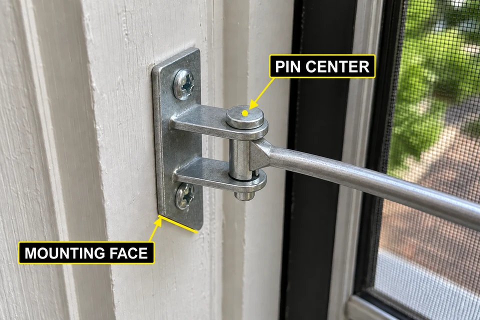
| Bracket projection | Mounting face to pivot-pin center | Projection in inches | Changes geometry even when screw holes match |
| Pin-center span | Jamb pin center to door pin center | Span, door position, and selected pin hole | A span without its setup condition is ambiguous |
| Operating clearance | Closest relevant parts during intended movement | Smallest observed gap and where it occurs | Closed-door clearance can hide later interference |
If the bracket offers multiple pin holes, note which one you measured. Photographing the assembly can help identify the references later, but take the dimensions directly. A photograph alone does not establish scale or depth reliably.
These measurements describe what is present. They do not prove that the original installation was correct.
Which Dimension Determines Part Compatibility
No single dimension confirms complete bracket compatibility. Mounting-hole spacing tells you whether the base matches the existing hole pattern. It does not tell you whether the bracket holds the closer in the required position.
After checking the hole pattern, compare the mounting-face-to-pin-center projection. Two brackets can accept the same screws yet place their pivot pins at different distances from the mounting surface. That difference changes the closer’s position relative to the door.
Check the pin interface as well: pin diameter, usable pin length, and the space available for the closer’s connecting end. Where the bracket has two ears surrounding the connection, the opening must accommodate the intended part without forcing or distorting it. Small interface dimensions may require calipers rather than a tape measure.
Record dimensions in inches using the same endpoints as the applicable drawing. Confirm mounting orientation and whether the base has the intended bearing surface on the door or jamb. A similar-looking base that bridges a raised frame edge does not reproduce a flat mounting condition.
Use these measurements to screen the fit, then confirm that the bracket is intended for the existing closer and door application. Do not enlarge holes, substitute a loose-fitting pin, or bend the bracket to make an uncertain match work.
How to Allow for Clearance, Compression, and Adjustment
Separate Setup Preload From Operating Clearance
With the bracket interface established, check the closer’s required setup condition. Some residential closers specify an initial rod extension while the door-bracket position is established. That extension establishes the prescribed starting condition; it is not a universal measurement.
“Compression” in this context concerns the closer’s specified setup or preload. It does not mean pushing the rod fully into the cylinder and locating the bracket wherever the parts meet.
Record any required extension using the endpoints shown in the instructions. Total visible rod length may include features outside the specified measurement. Likewise, do not substitute the distance between bracket edges for a required pin-center span.
Keep measurement resolution separate from installation tolerance. Being able to read a tape to a small fraction of an inch does not tell you how much placement error the hardware permits. Use published allowances where provided; do not invent a margin when none is stated.
Check Travel Before Speed Adjustment
A closer can appear aligned with the door closed and still contact trim, bind at a connection, or reach its travel limit as the door opens. Check the intended movement only after the hardware is secured as instructed. Do not swing the door against a bracket held by hand.
Watch the cylinder, rod connection, and bracket through the movement. Record where the smallest clearance occurs, rather than assuming it occurs with the door fully closed. Stop if movement requires force or the assembly contacts surrounding material.
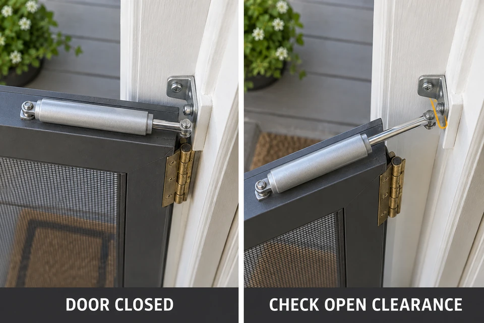
Where slots or alternative pin positions provide adjustment, follow the specified starting position. Do not automatically center every slot or use all available adjustment to compensate for uncertain measurements. Adjustment travel is a designed feature, not a substitute for correct placement.
Do not force the closer to the end of its stroke or rely on it in place of an appropriate opening restraint. Once geometry and movement are established, you can adjust the closer’s closing speed. The speed valve cannot correct misplaced pivots.
How to Measure When the Old Part Is Bent or Missing
Here, the old part means the mounting bracket. The closer itself must still be intact for these positioning checks to apply.
A bent flange is an unreliable reference for its original projection. Even if its mounting base remains flat, the pivot hole may have moved. The base might preserve useful screw-hole spacing while no longer preserving the dimension that positions the rod.
If you are dealing with a closer arm or bracket that keeps bending, separate that deformation assessment from the measurement task. Copying the distorted part can carry its error into the replacement position.
When the bracket is missing, inspect old screw holes, paint outlines, and wear marks as clues. They can indicate where something was attached, but not whether its position was correct or which bracket projection was used.
Rebuild the reference from the instructions for the existing closer and the relevant door construction. Identifying the installed hardware serves to locate its drawing; it does not require choosing a different closer model.
Measure from the stable mounting surface and the normally seated door using the specified setup condition. Mark unresolved dimensions as unknown. Do not estimate them from an angled photograph or borrow dimensions from a visually similar assembly.
If the required geometry cannot be established, pause before drilling or forcing the parts together. If the mounting surface moves or the rod is bent, the assumptions behind this measurement process no longer hold.
Measurement Errors That Cause Poor Fit or Repeat Failure
Before accepting the position, compare your recorded endpoints with the drawing once more. Measuring to a bracket edge instead of a specified pin center can shift the interpreted pivot position. Measuring from trim instead of the named jamb reference can introduce another offset.
Matching only the screw holes can preserve the wrong projection. Recording a span without noting the door position makes later comparison unreliable. Copying a bent bracket can reproduce distortion, while checking only the closed position can miss interference during opening.
Any of these errors can contribute to poor fit or repeated loading. They do not, by themselves, prove the cause of an existing failure.
Accept the position only after this short check:
- The correct drawing, reference surfaces, and door/setup state are recorded.
- The bracket interface and pivot projection are verified.
- The required setup position and secured operating clearance are checked.
- The mounting remains stable and the door completes its intended movement without forced travel.
Resolve an unknown measurement before committing to the position. Once those checks agree, a remaining symptom belongs to a different decision: if the closer still will not pull the door shut, continue with closure diagnosis rather than moving the bracket by guesswork.